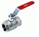
- Direction control valve
o Solenoid valve
These valve means to open or close the flow path, that in effect of this , motion of system will start or stop .
The name of the valve depends on the number of switch positions and number of openings. For example, 2/3 solenoid valve (called three-two), means the valve has 3 openings and two switch positions . However, in naming a valve , the static position of the valve is expressed . For example, 4/3 valve with normally closed position. Common types of solenoid valveس are 5/3, 5/2, 4/3, 4/2, 3/2, 2/2 . Valves stimulation is possible with the variety types of manual , electrical , mechanical , hydraulic and pneumatic mechanisms.
o Switching valves
These valves are used for switching flow. The valves can be used with sitting or sliding mechanism. Switching valve can decrease or increase the flow path with no steps.
o Check Valve
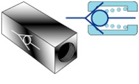
Check Valve is an instrument that allows the flow path just in on direction , and from the other direction , it prevents the flow path and because of this, they are named return obstacle valves too.
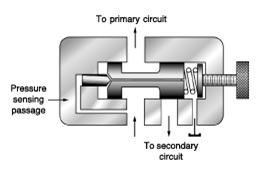
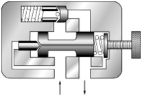
- Pressure control valves
Pressure control valve in hydraulic systems is a mean which we can determine the pressure in the system or limit or reduce it and generally, the pressure in the system is affected by it.
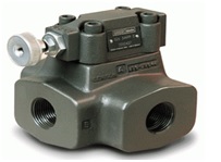
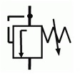
o Relief valve
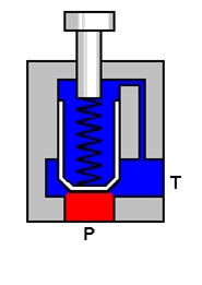
This valve is used to limit pressure in hydraulic systems and can protect system against increasing pressure by load excess. The maximum pressure set at this valve is usually more than the maximum working pressure of user.
Relief valve is the most used type of pressure control valves. this valve is used to protect pump and system components against pressure increases. Also, The maximum power of cylinder and hydromotor is limited by this valve. Relief valve is a valve with closed normal position that when the pressure reaches a certain amount, the excess of flow from the pump is returned to the tank and keeps the pressure amount in a set amount.
Relief valves are classified due to the amount of flow rate to two types of normal and pilot. The pilot type works as combination of two valves and is possible to pass a very large amount of oil.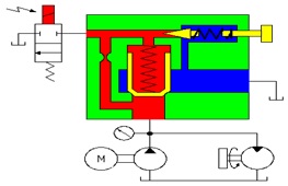
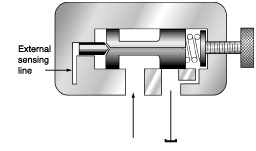
o Pressure reducing valve (pressure regulator)
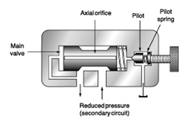
The pressures reducing valve is used to reduce the inlet pressure to the consumer and to keep the amount of output pressure fixed, even with the input pressure swings. In order to detect circuit signal between the relief valve and pressure reducing valve two points must be considered :
- Relief valve is closed in static position and control signals comes from the entrance.
- Pressure reducing valve is open in static position and control signal comes from the output.
o Pressure dependent control valve
When the pressure in a hydraulic system reaches a certain level, the pressure dependent valve will be opened because of pressure function and allows current to flow to other parts of the system.
o Counter balance valve
This valve makes the required resistance against the flow path in one direction but from the other direction allows it pass.
o Unloading valve
This valve discharges the sent flow from pumps in the tank under zero pressure when the hydraulic system isn’t under a load and the usage of power and heat dissipation of discharging fluid by Relief valve.
- Flow control valves
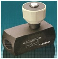

The flow control valves are used to regulate the speed of cylinders and hydraulic motors by varying the input or output flow rate.
Flow control valve makes the passage of oil tight or loose with opening or closing a guttural. tightening of the passage causes increase the pressure of passing oil. The intended pressure causes opening the pressure breaker valve at the beginning of its path. As a result, excess oil returns to the tank through this valve. Since the oil is discharged by pressure, the existing power in it will change to heat and causes the increasing the temperature of oil.
- Cylinder speed control by using Meter In and Meter Out methods
In Meter In, by creating limitation in the input ports of the cylinder, and it reduces the amount of input oil and thus the speed of the cylinder is set at an optimal level.
In the Meter Out, creating limitation is performed at the output ports of cylinder.
Both of these methods are common to control the speed of hydraulic systems. In using Meter Out method in the cylinders, making excess pressure on the piston rod must be noted. Instead, this method makes excess oil discharge from the Drain port of the motor in hydro motors.